I have started a new adventure learning electronics, and I found a good problem to solve with electronics, control my fan remotely. The purpose was to learn electronics more deeply instead of using a simple Arduino board.
The problem
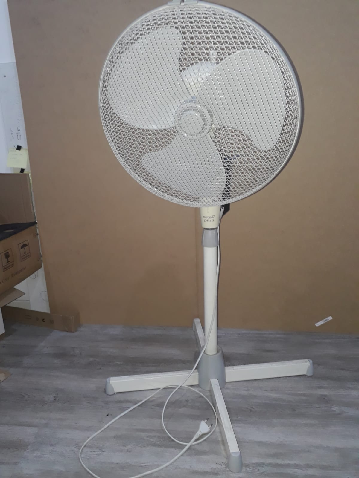
I had an old fan 10 years old, it is Cata fan with model DP40. I wanted to turn on/off and control the fan speed. My fan has four states: off, velocity 1, 2 and 3. I wanted to control my fan remotely and manually at the same time, for example, you put the speed two manually because you were standing, but after some minutes you want to turn off or change to the velocity one with the remote control.
How my fan works
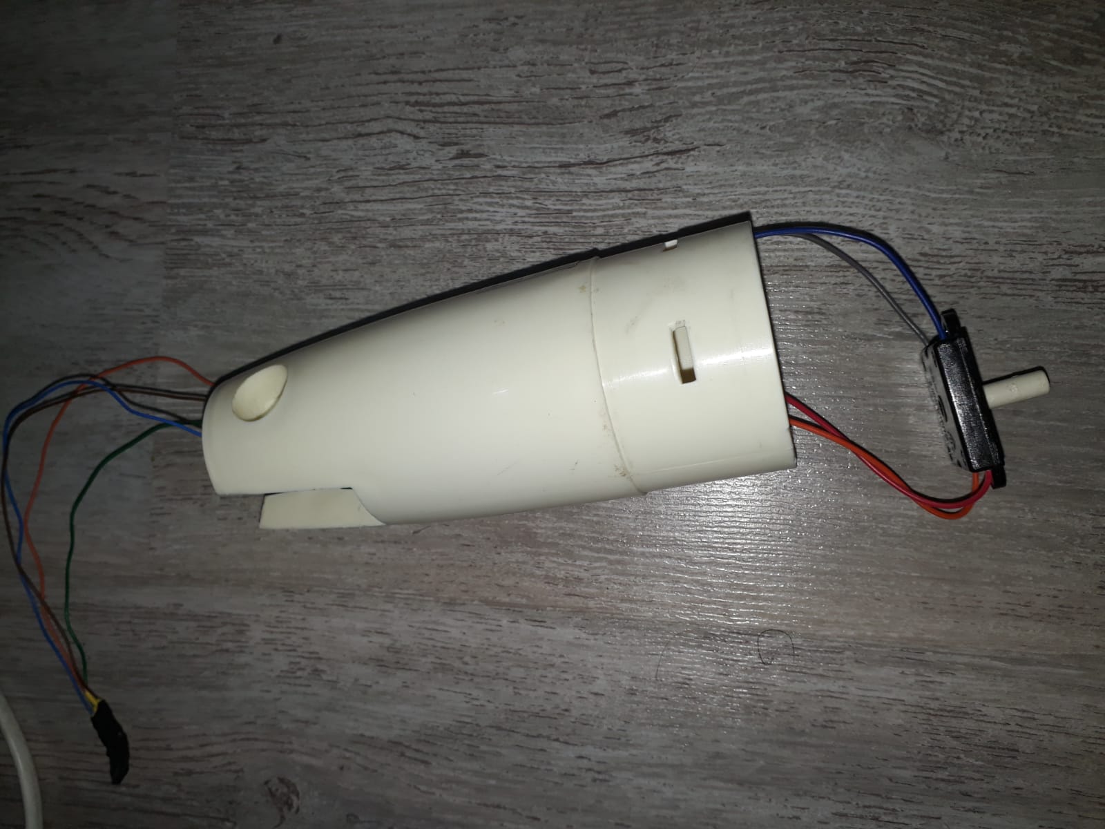
Before start coding or doing something else, I needed to know how my fan worked because I don’t know how usually fan works or how my fan changes the speed.
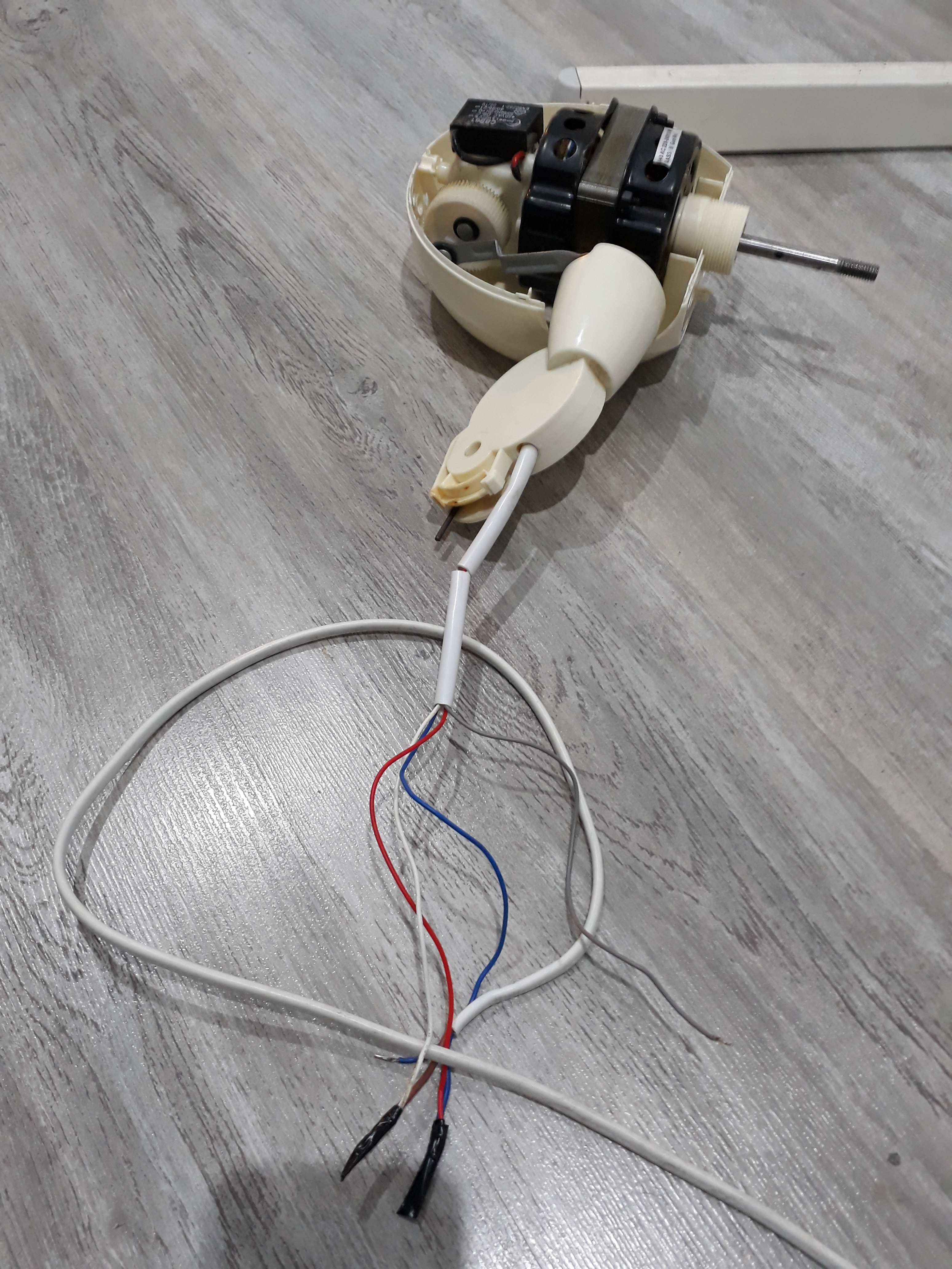
I disassemble my fan and I saw a switch with three channels where the AC Line load it is connected with three different wires depending on the speed, that is how my fan works, giving volts to three different wires.
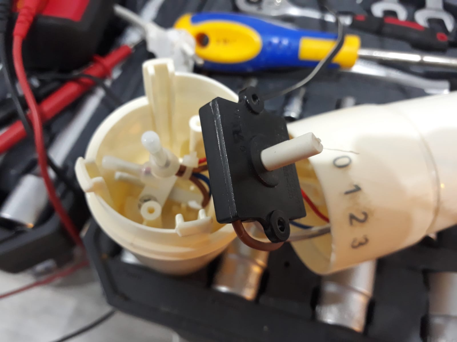
When I saw the switch with three channels, etc. I suppose how it worked but I needed to try it connecting the AC line wire to one of the speed wires to confirm that it worked, this is how it looked like:
First version using relays
After knowing how my fan works, I knew how to solve the problem using relays to simulate the three channel switch by remote control. I had experience controlling relays in Arduino with small projects then I knew how to use relays in Arduino and it is effortless, activate or deactivate by an Arduino pin.
I wrote a simple program to switch the relays depending on the infrared input, here you can see how the infrared sensor works.
And this is how my fan looked like:
Don’t use relays use Transistors!
I didn’t like relays because make noise, they are huge and I need three relays for the different states. After looking for a solution which replaces a relay without sound and I found the word “Transistor”, wow! I learned a lot about transistors at the University! Everything has been made with transistors, microcontrollers, computers, your coffee machine, everything has one!
Then I started to read a lot about it, there are many transistor categories NPN, PNP, BJT, Mosfet, SCR, etc. I learned about BJT and Mosfet at the university. After read about it I needed a BJT Transistor but which one PNP or NPN?.
![]()
To replace a relay I needed to give +5v as an input and switch on the relay/transistor and let the current-voltage flow between Collector and Emitter, for that case I need NPN because with a small pulse I can open or close the switch transistor, but with PNP I need to apply a negative voltage to close the transistor, I wrote about BJT transistors here
Then I made a small example replacing the relays by Transistors and I used leds to emulate the three different speeds.
![]()
Remote and manual control
Okay, I can control my fan with the remote control but what about to use it with remote control and the three channel switch as manual?. After thinking about how to separate the manual feature from a remote control feature using the Arduino. I realize I couldn’t do easily because I need to know the state of the manual mode and the remote mode for interrupting the voltage from the three channel switch when changing the speed from the remote control but the physical switch is in the channel 1.
Finally, I connected the switch to the Arduino using 5v DC instead of 220v AC and I found a problem, the switch doesn’t work correctly with low voltages and sometimes without touch the switch some output channels received 5v without select that channel. The reason was the switch isn’t designed to work with low voltages then sometimes let the voltage fluent to other channels without selecting them.
I solve the problem using analog input instead of digital input, I was using the digital input to know if a channel is selected when the channel receives 5v in the input, but sometimes there is 5v without doing anything, then I used analog to be more precise and do a simple calculation.
boolean isHigh(int pin) {
  float manualFast = 0.0;
  for(int i = 0; i < SIGNAL_QUALITY; i++) {
   manualFast = manualFast + (analogRead(pin) * (HIGH_VOLTAGE / 1023.0));
  }
  return (manualFast / SIGNAL_QUALITY) == HIGH_VOLTAGE;
}
With this method, I calculate the average of the voltage to know if it is a HIGH (5v) or LOW (less than 3.5v) depending on the quality measurement, with this calculation if the channel isn’t selected I get 4.5 or 3.5 which means it is LOW and when the channel is selected I get 5v all the time.
This is the result of combine remote control and manual.
Real world
It seems I finished to design my circuit and I was able to try it with my fan instead of the small leds. I needed to buy a transistor which could support high voltages and current, at least 220 volts and 16 A.
I bought a MJE18008 NPN Transistor which support 1000v !! it should be fine!, I connected the Collector and the Emitter to my home electricity and it exploited.
![]()
Why? It supports 1000v !! after reading a lot about it I found the answer, A transistor it is unidirectional, not bidirectional, It doesn’t work with Alternating current! oh god. After broken two transistors, I learned the difference between DC and AC.
Triac
Triacs are the answer to my question, “which one is the relay substitute?”, the Triac!
A triac is two transistors in parallel in different directions to give it the bidirectional feature. The triac has the same functionality as a typical transistor but works with AC loads and there isn’t a difference between “Collector” and “Emitter”, it just calls “T1” and “T2”.
I bought a BTA16-600B Triac and I did the same experiment as the transistors and It didn’t exploit!. If you want to know more about Triacs, I wrote about it here.
Control high voltages with Triac and Arduino
I had a Triac which didn’t exploit, I had an Arduino with the program, then I only needed to connect to the 220v, yeah! Finally!
I was going to connect to the 220v and I read about how to connect all and I saw this schematic in a video which explains that there is a dangerous part where you need to connect -5v to neutral 220v.
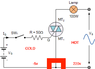
I didn’t want to burn my circuit and Arduino or something like that and I started to read more about how to connect high voltages with low voltages and I found the optocoupler.
Optocoupler
You need an optocoupler when you want to control high voltages with small voltages like a microcontroller, the optocoupler will isolate the high voltages (hot side) from the low voltages(cold side).
Then I can use it to control the fan speed using triacs in the hot side with the microcontroller pulse in the cold side, this is an example of switching on a bulb or fan with only one speed.
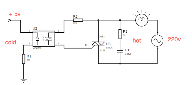
To test if it is working, I did a small circuit which uses 9v as input with a limiter to 5v and added a MOC3021 optocoupler to try if I can turn on/off a bulb with the optocoupler. It worked well, then I decided to replace the bulb for my fan, and It worked too!
If you want to know more about optocouplers, I wrote it about it here.
Designing the circuit
At this point, it seems I can connect my circuit with 220v loads. Before to connect the circuit in real life I wanted to do some test with any kind of emulator to know if I could burn my circuit or if something it is wrong.
I installed Fritzing, but it was hard to import custom components like my Triac BTA16…, I installed Kicad which is free and has a big community but it doesn’t have a simulator, but it is cool to design.
Finally, I found Proteus which it is the big and complete software to design and simulate circuits I have seen, it has a lot of functionalities included creating invoices with the list of components you used to design your PCB.
It has a small problem, It isn’t supported macOS then I used wineskin to install proteus in mac following this video.
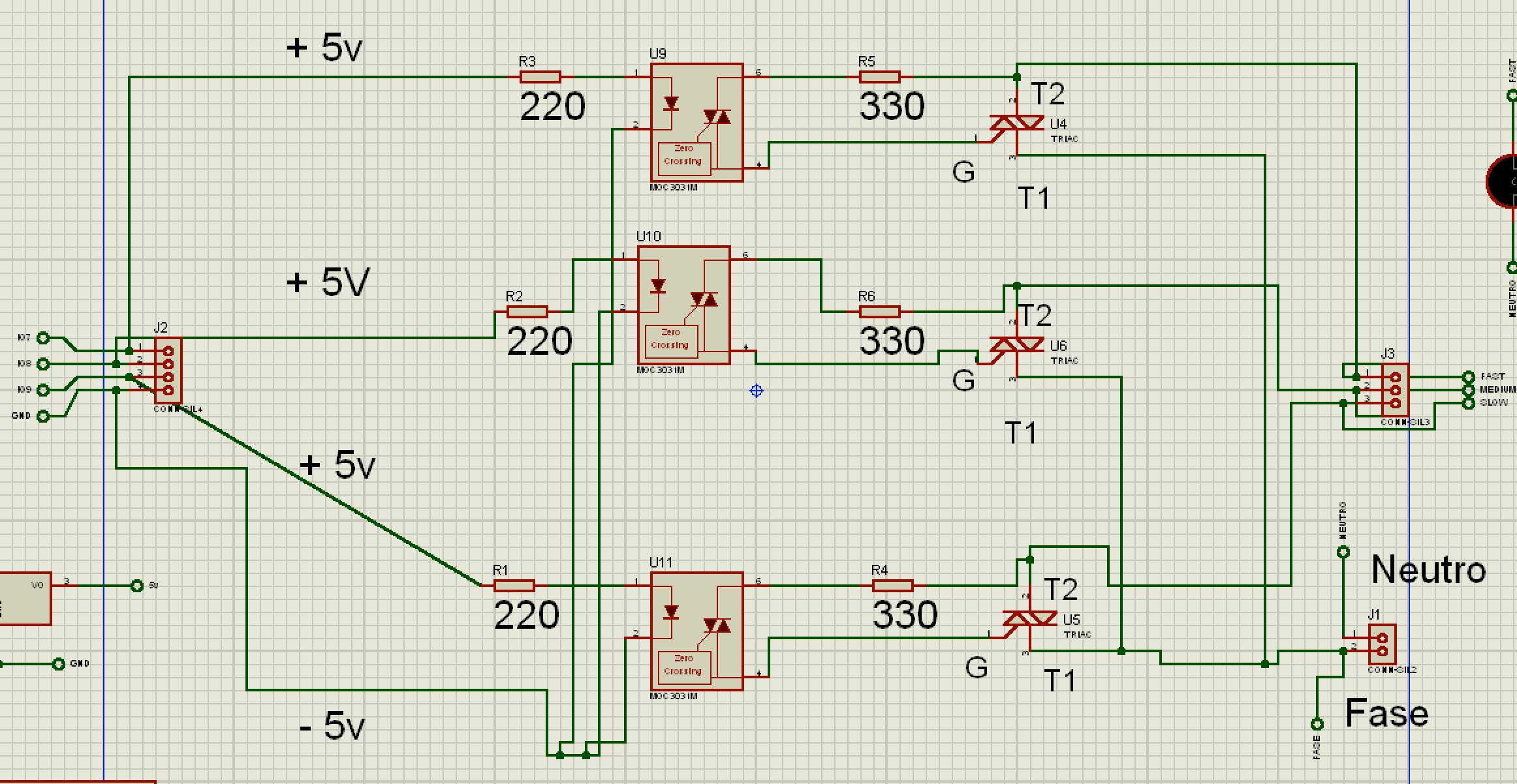
After some hours in front of Proteus, I designed my circuit and PCB. I have split the circuit into two parts, the “Arduino” side with the microcontroller atmega328 and the rest of the circuit with the triacs and the optocouplers.
This is the circuit where are the triacs and the optocouplers, I have used block terminals to connect external loads like bulbs or fan wires.
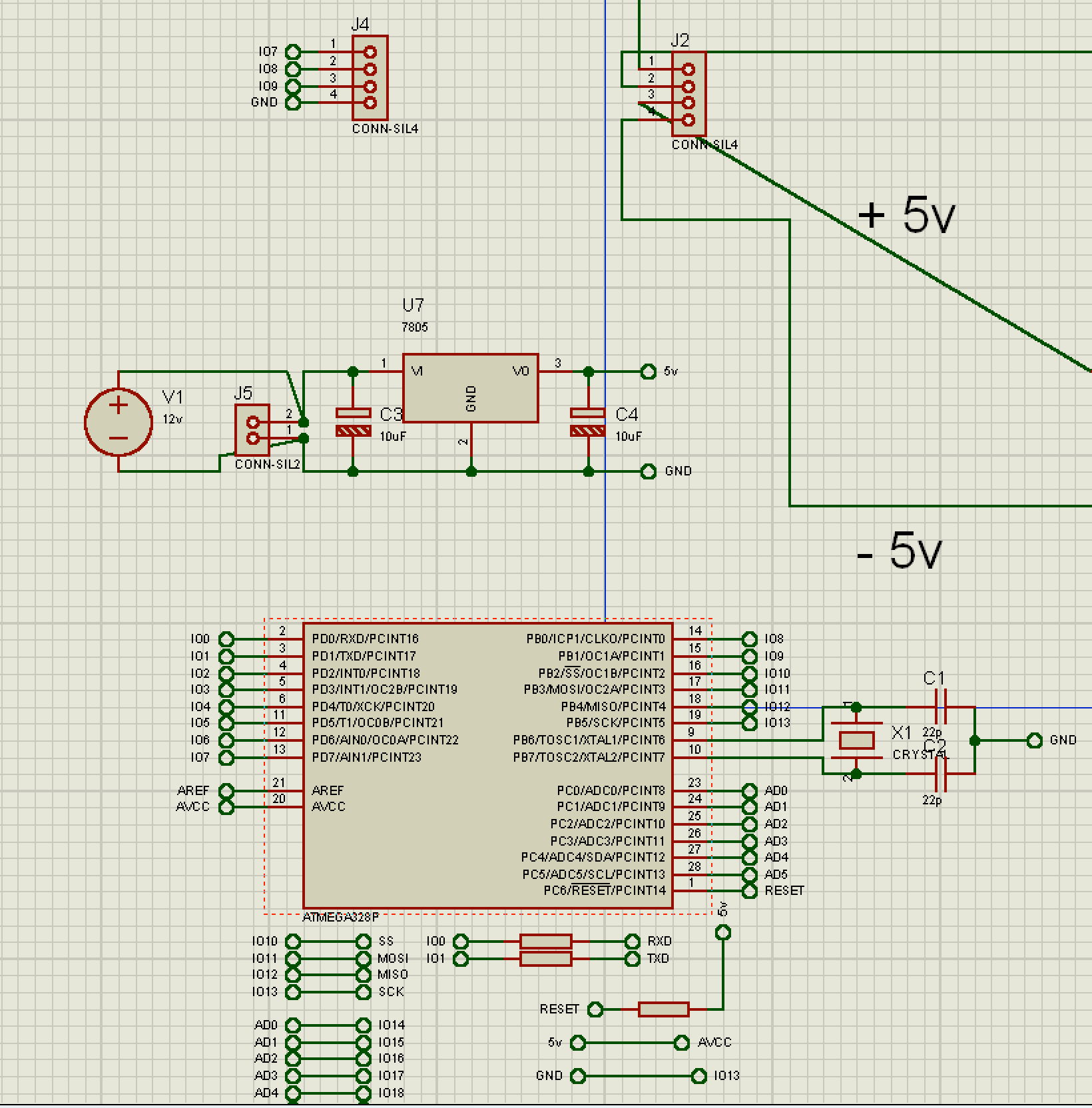
Here is the microcontroller atmega328 with an L7805 limiter.
After that, I created the PCB connections with the design of the two parts.
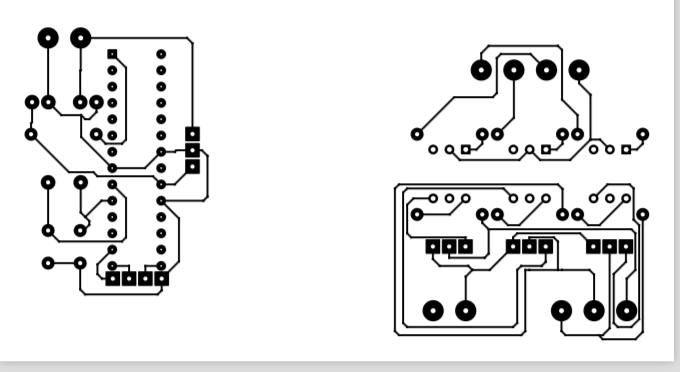
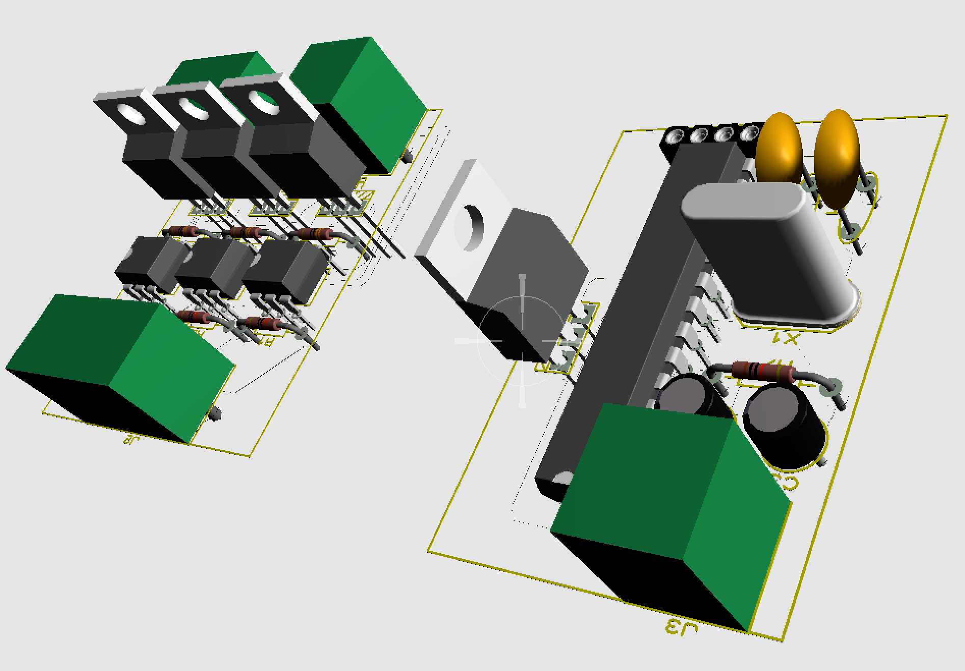
This is the 3d visualization of the PCBs.
Connecting the design
After design, simulate my circuit and be sure my circuit will work, I created a test circuit with the breadboard and used bulbs instead of the fan for the fist time.
First, I needed to create my own Arduino board only with the atmega328 microcontroller, I wrote about how to use the microcontroller and how to install it the bootloader for install any application into it. I used atmega328 because it is easily to me using something I already know using the Arduino board to program the app and load it to the microcontroller. I have a plan to use another smaller microcontrollers to simplify the circuit.
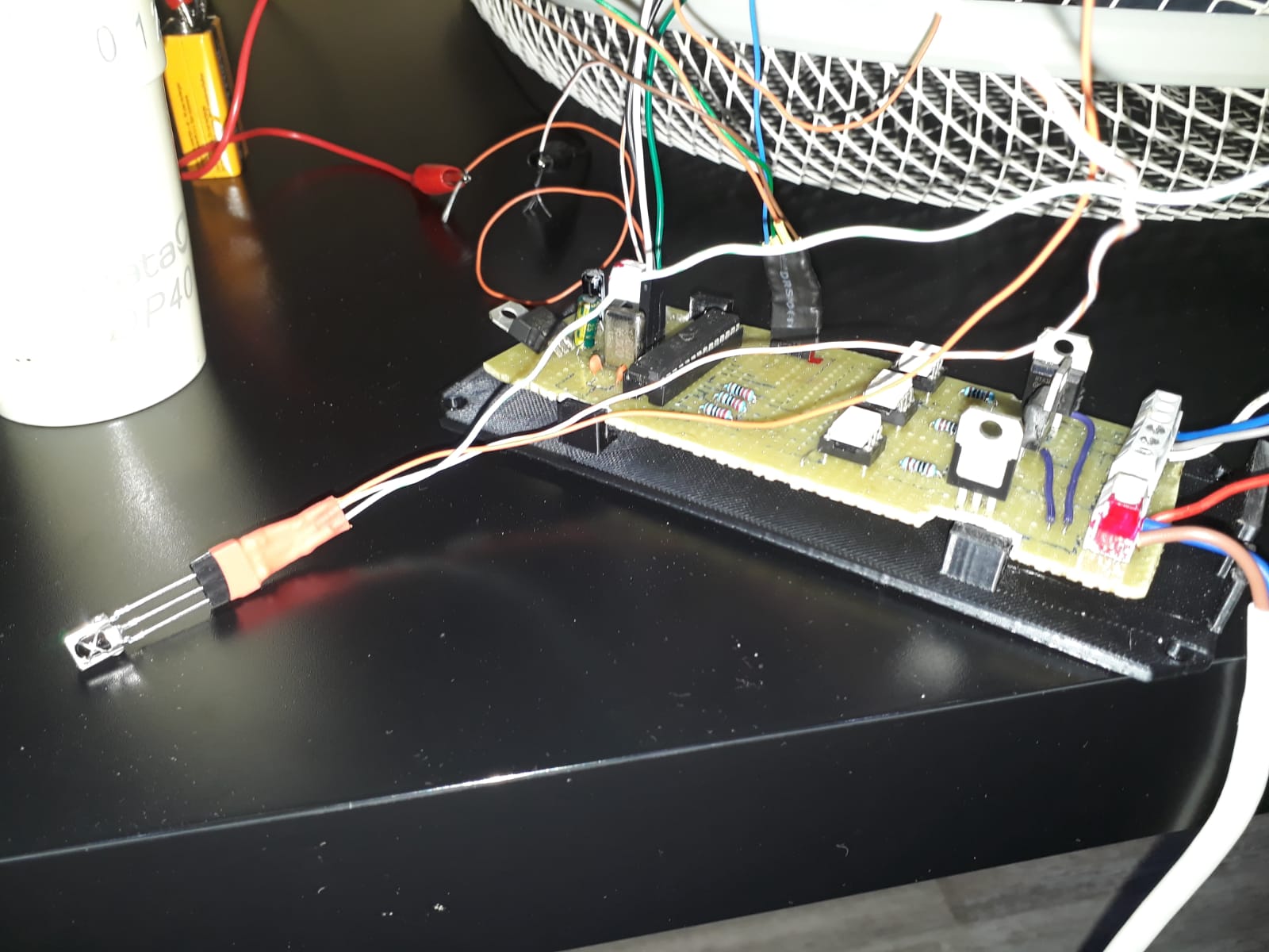
This is how my circuit looks like:
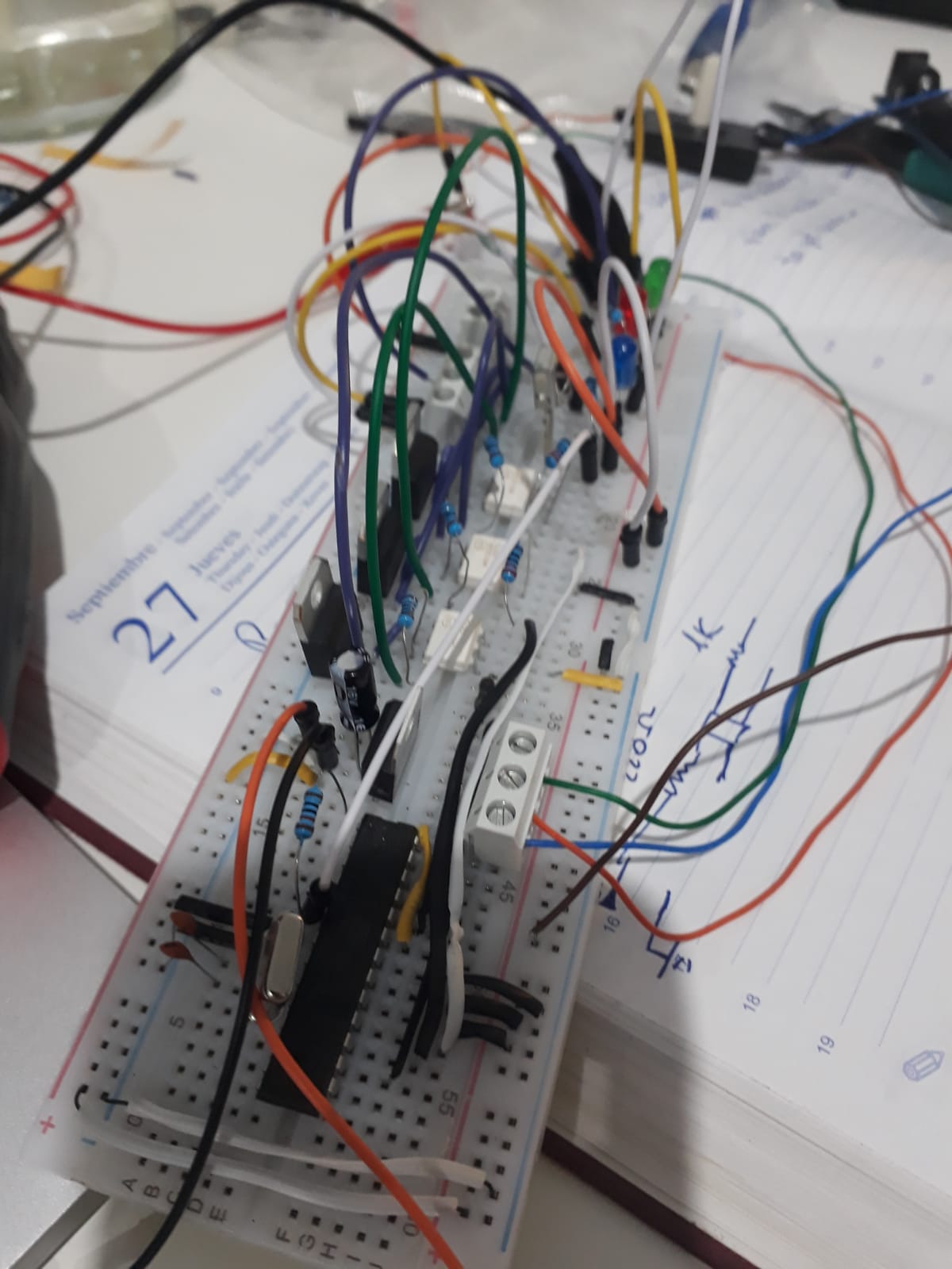
And this is how it works:
Soldering my circuit
I could order a PCB with my design but it would cost too much just for one PCB and I preferred to learn how to solder for future projects.
I started to design in the paper how to organize the tracks in the typical PCB for soldering. There isn’t too much to say, at the beginning, it is hard to solder because the tracks are very near and you don’t want to create a very big circuit. After spending some time soldering I got more experience and started to do a little bit better. I spent 10 hours soldering my circuit :(.
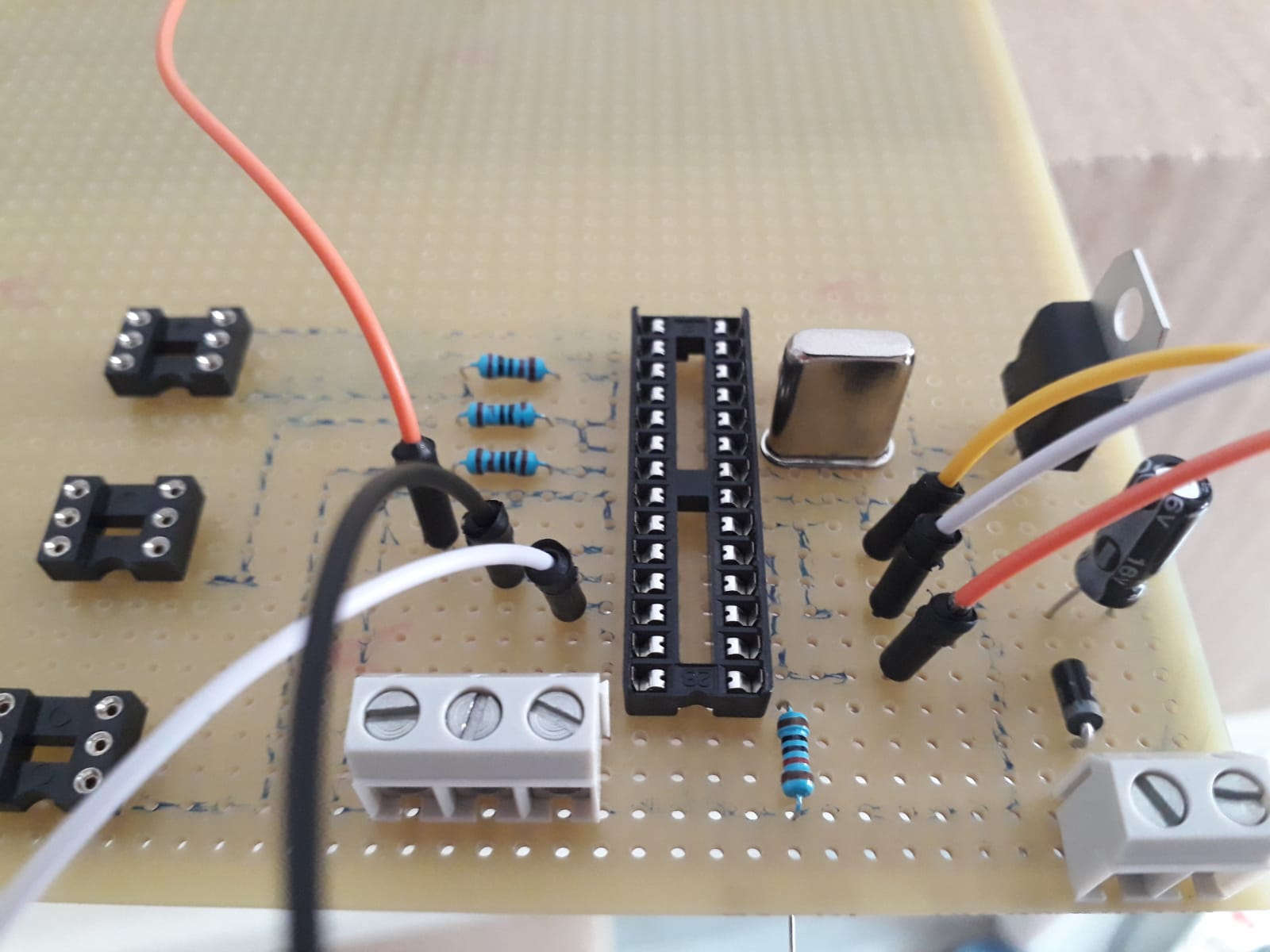
I began with the cold side and I used wires as references sometimes, this is an example.
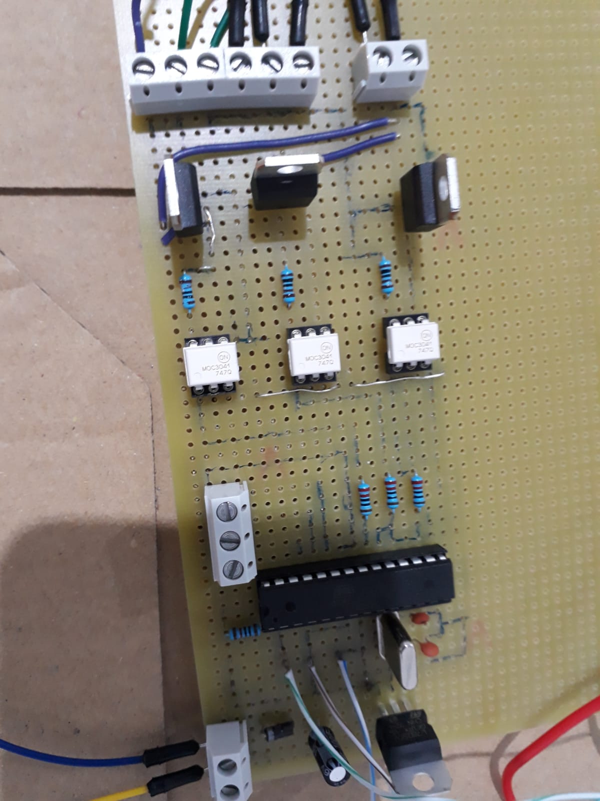
I used sockets to replace the microcontroller or the optocouplers if something went wrong. It is useful to test your circuit too, but I learned this after.
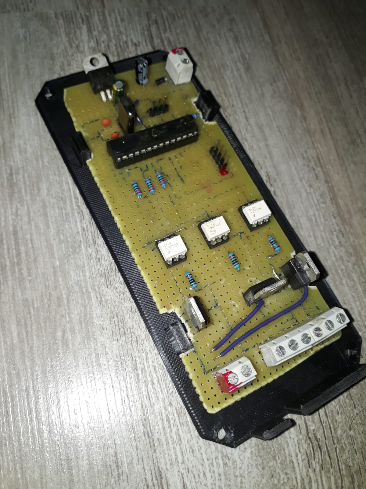
My circuit front side.
Back side.
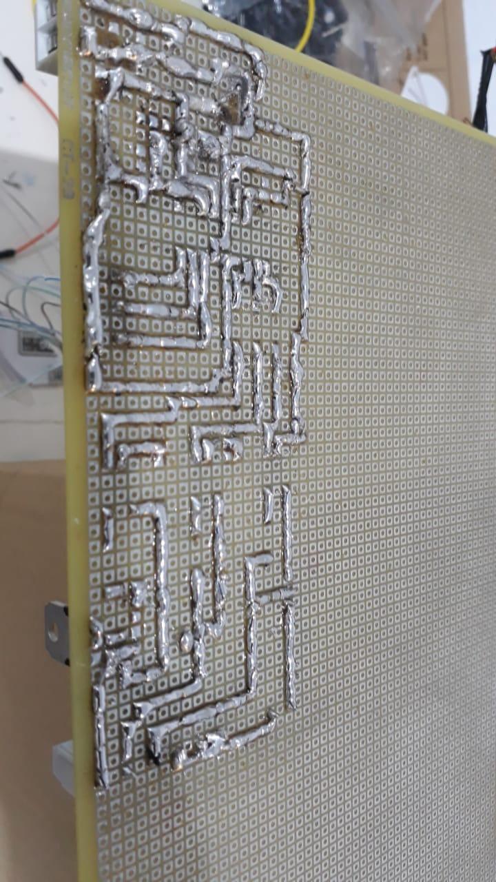
For the hot load, I have used wires in the front instead of solder in the back for more safety for the 220v Line AC.
It didn’t work after solder it
After solder it, it didn’t work! :( Thanks to the multimeter, I can test it using the diode mode to know if some tracks are bad solder or something like that.
I did some tests with the multimeter and fixed some things I was wrong, but when I tested all with the multimeter it seems it should be ready it still not working, then I started to do a test without the microcontroller.
I used the socket DIP28 to emulate the operation of the microcontroller giving 5v in the pin I wanted to test for example, I used the pin 13 to close a triac and I put 5v in the pin 13 but the light corresponding to the pin 13 stills turned off.
Finally, I found the error, it was related with the two capacitors the crystal oscillator of 16MHz needs to work, I connected the input of the capacitor with the output of the same capacitor directly, then the capacitors don’t work and the oscillator neither.
Protect your circuit
I was worried about how near the tracks of the hot side of my circuit are, thinking about possible short-circuit. I found a Protective Layer polyurethane insulation to isolate the circuit tracks.
You just need to spray it on the tracks.
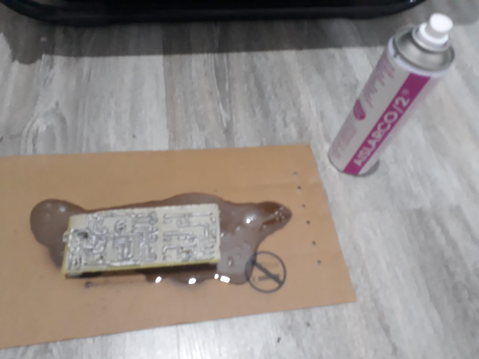
Sorry for the bad quality :(
Design the circuit enclosure
I wanted to create an enclosure to my circuit because it is very dangerous to connect that circuit without protection, then I decided to install Fusion 360 and start to design my enclosure.
I tried to create my circuit smaller to put inside the current structure of my fan but it was impossible creating a circuit soldering with three triacs and the small structure of the fan.
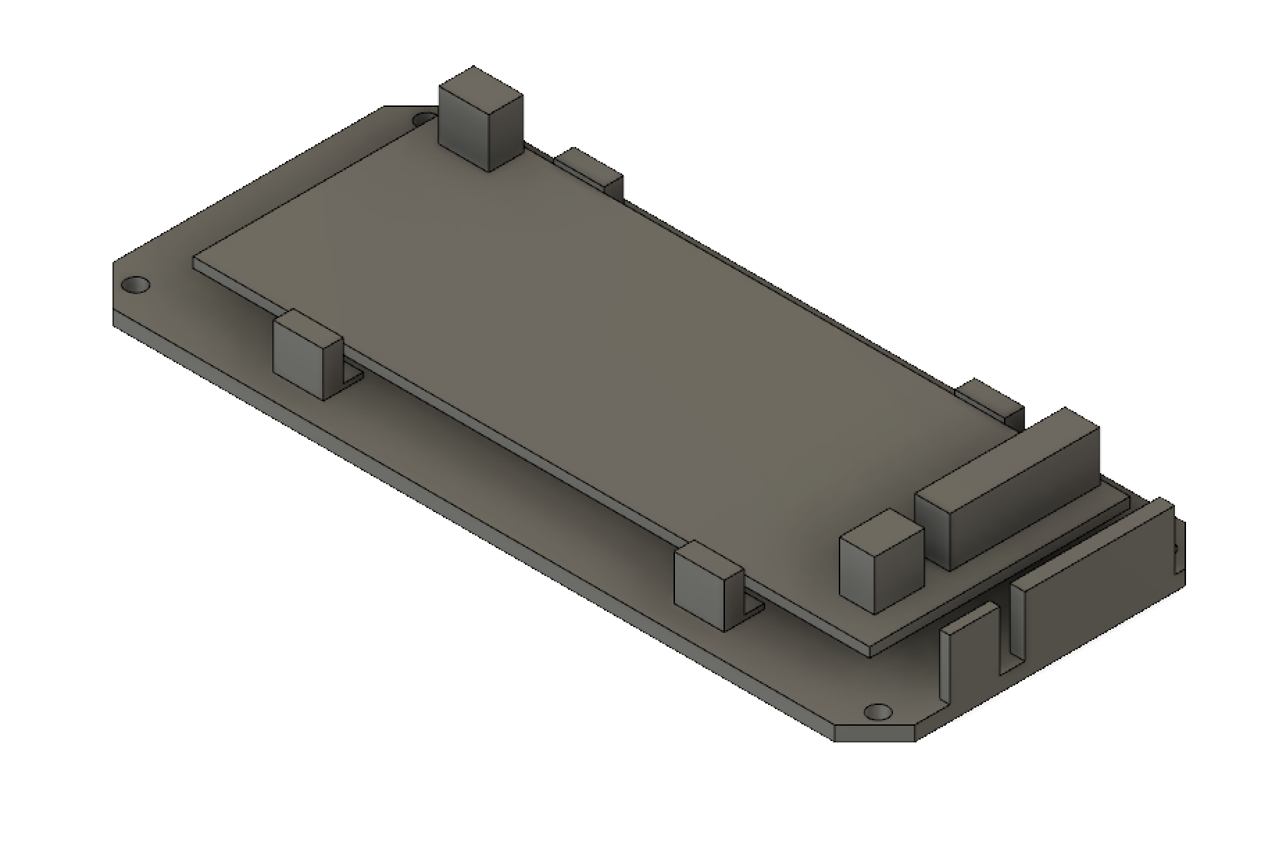
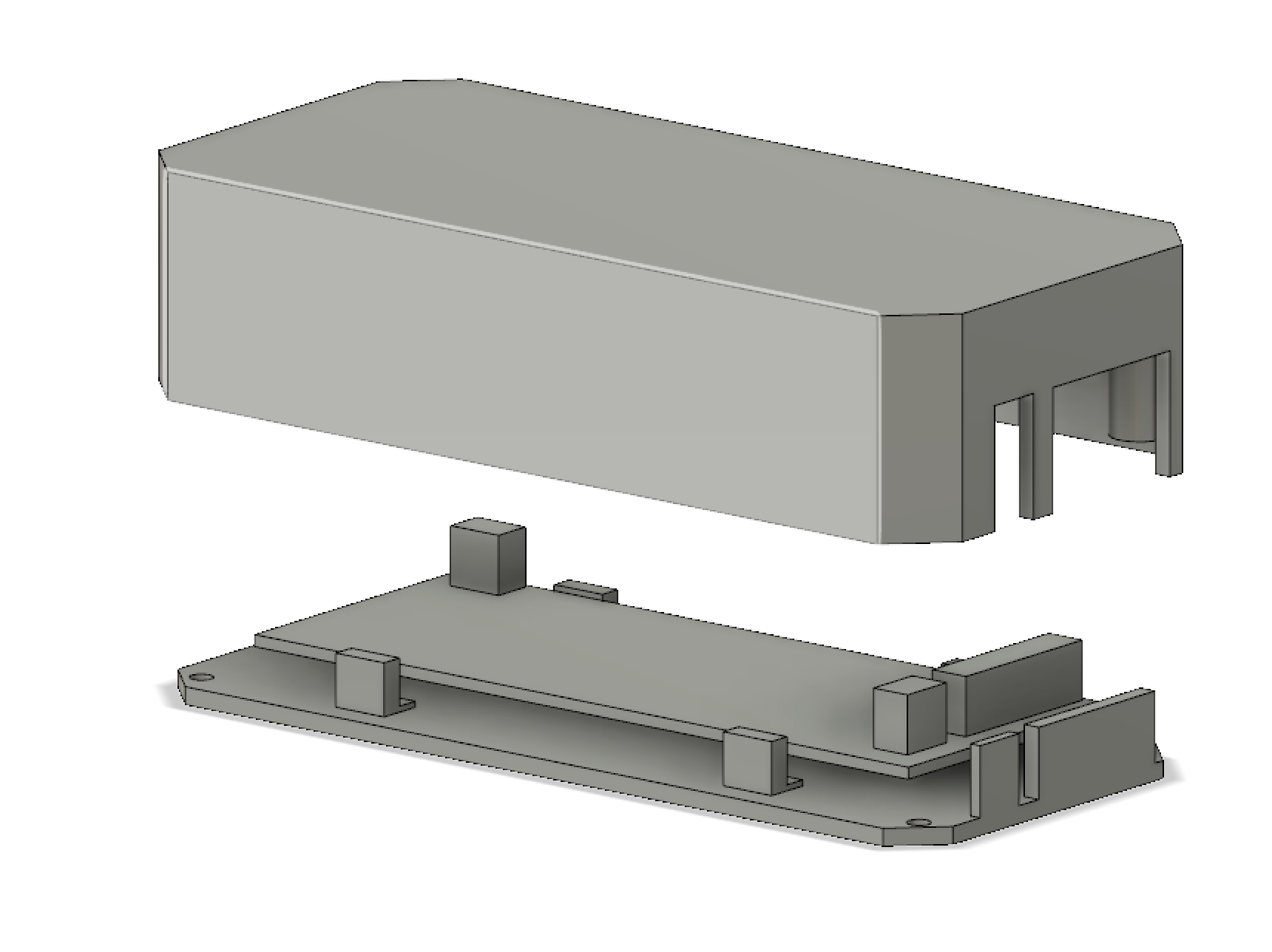
I added my circuit into the Fusion 360 to know it will fit into my enclosure and has an example to create the base. I added it without all the details because I only need the rectangle and the blocks as reference.
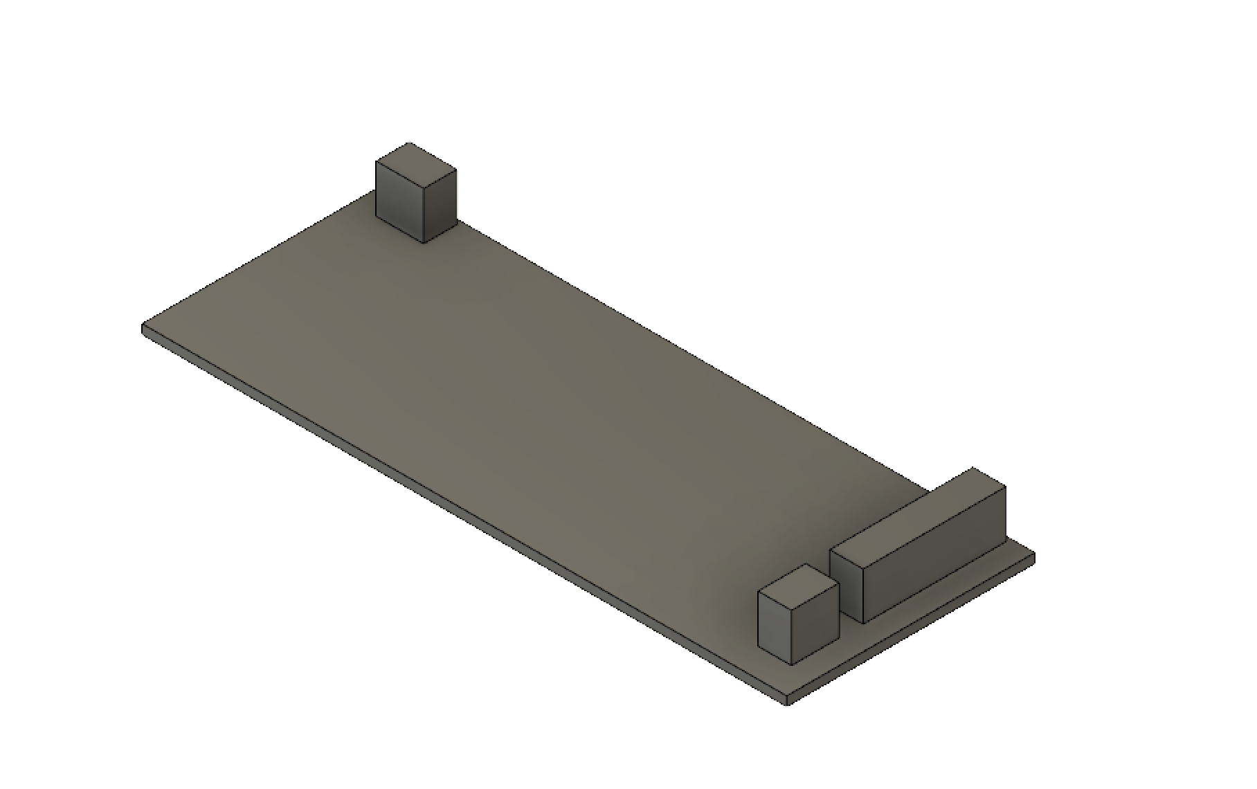
The base it was designed to put the circuit already connected with the wires, it is easy to manipulate the circuit, I added small parts to hold the circuit in the base.
The lid just has four holes to put the screws and some parts without wall to assemble with the wires already connected to the circuit.
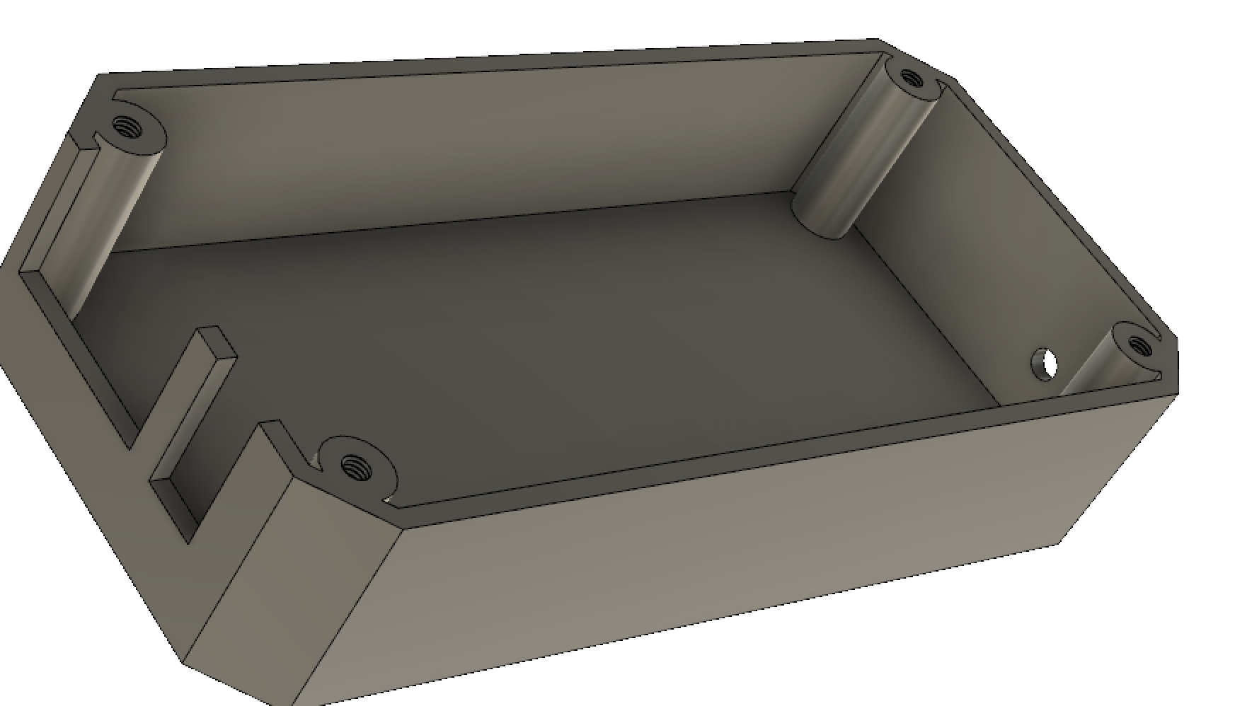
This is the final result, this is the enclosure open.
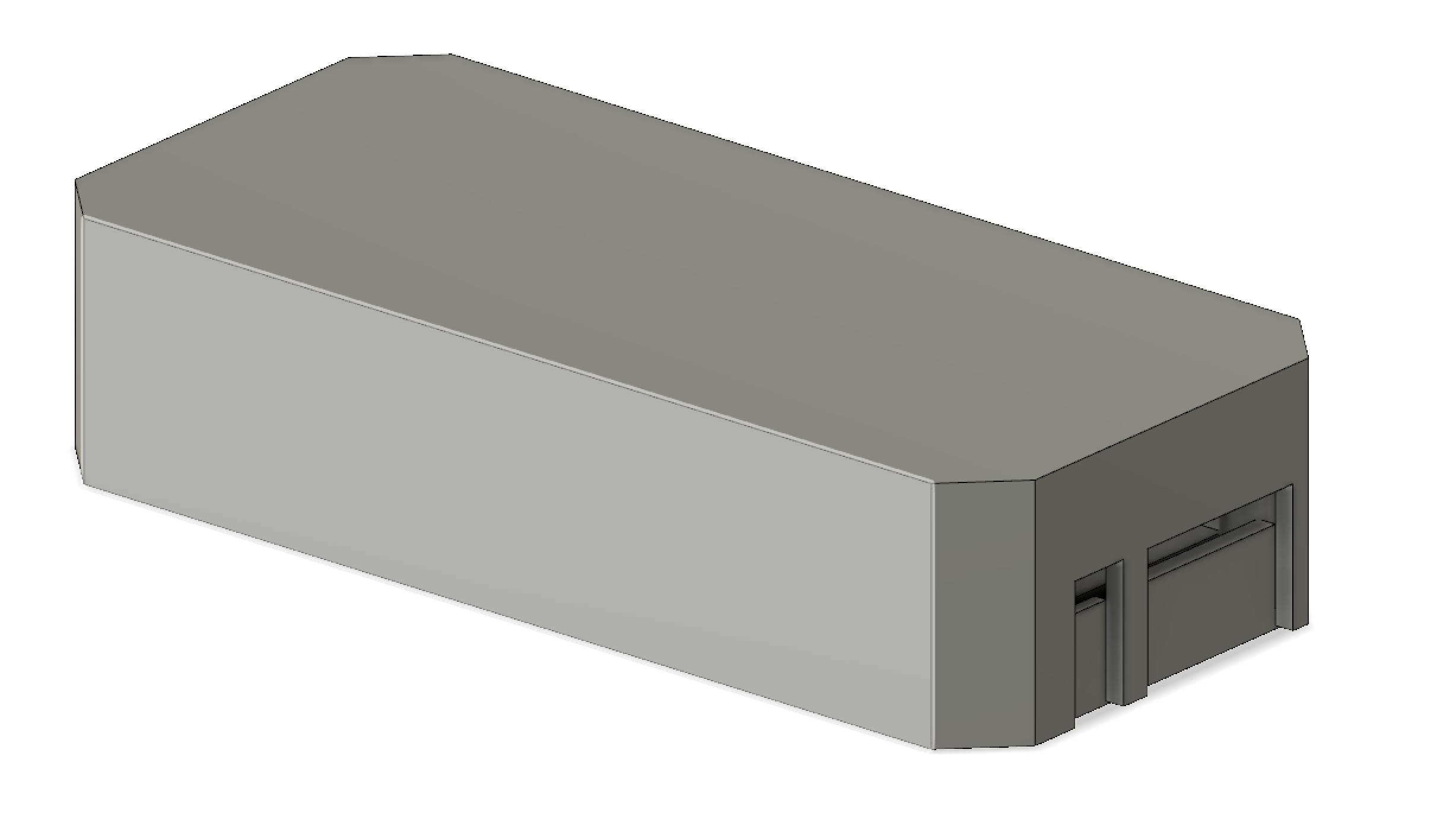
and here is closed, note that there is space for the wires.
I have learned a lot about modeling in 3D in fusion, I have made another enclosure after this one for other projects that I will show you here :D.
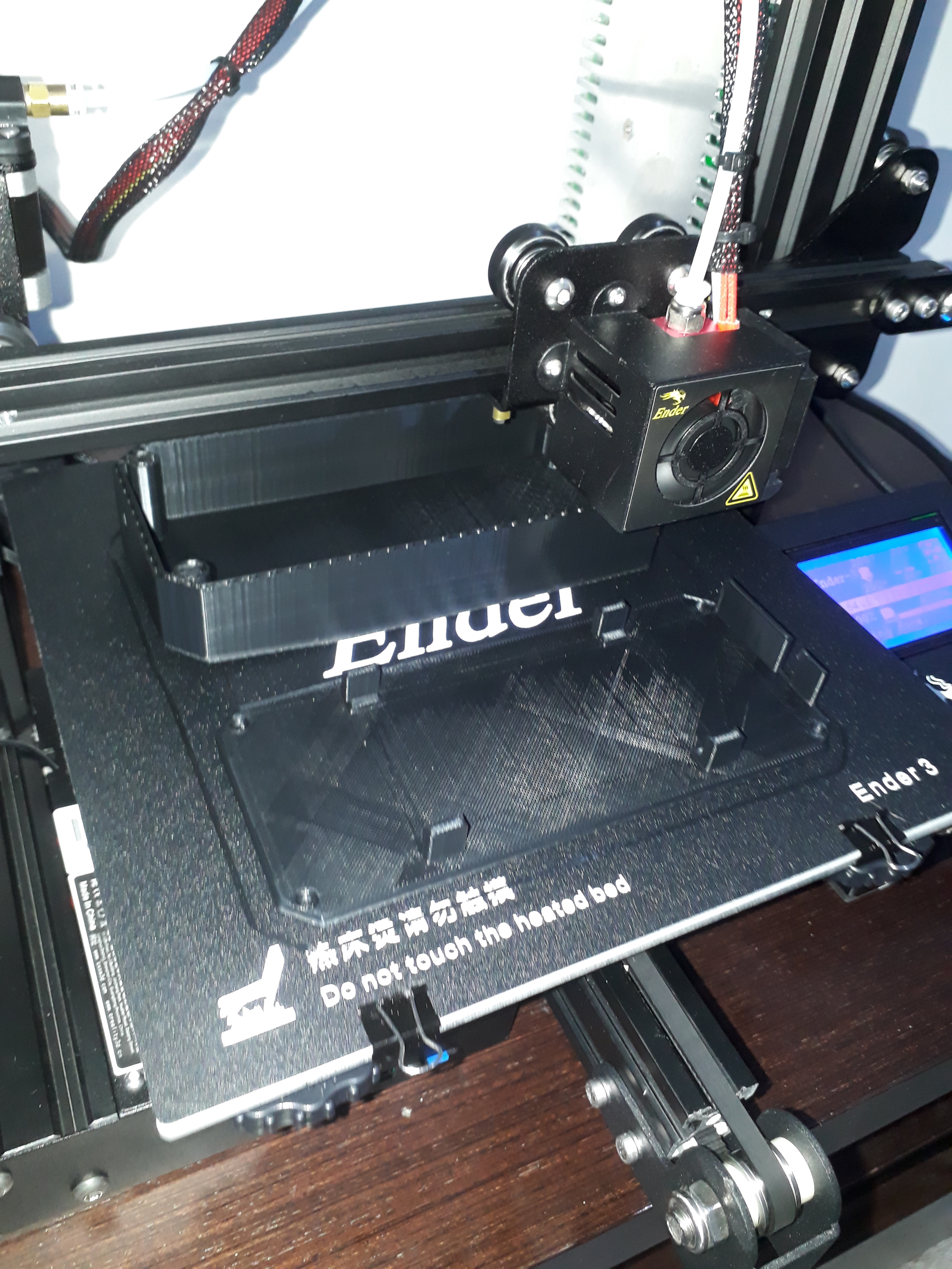
Enclosure printing
Well, It was time to print the enclosure, I didn’t know how to use a 3d printer (I bought Ender 3 printer for print the enclosure, and of course for future projects…) but after spending some time printing examples to not waste too much filament,
I send the 3d design from Fusion 360 to Cura which is the software to configure the 3d models to 3d printer commands like hot the nozzle 200º, start in the point x and y, etc. You can sort the components to the bed printer as well, change the position 90º or anything else.
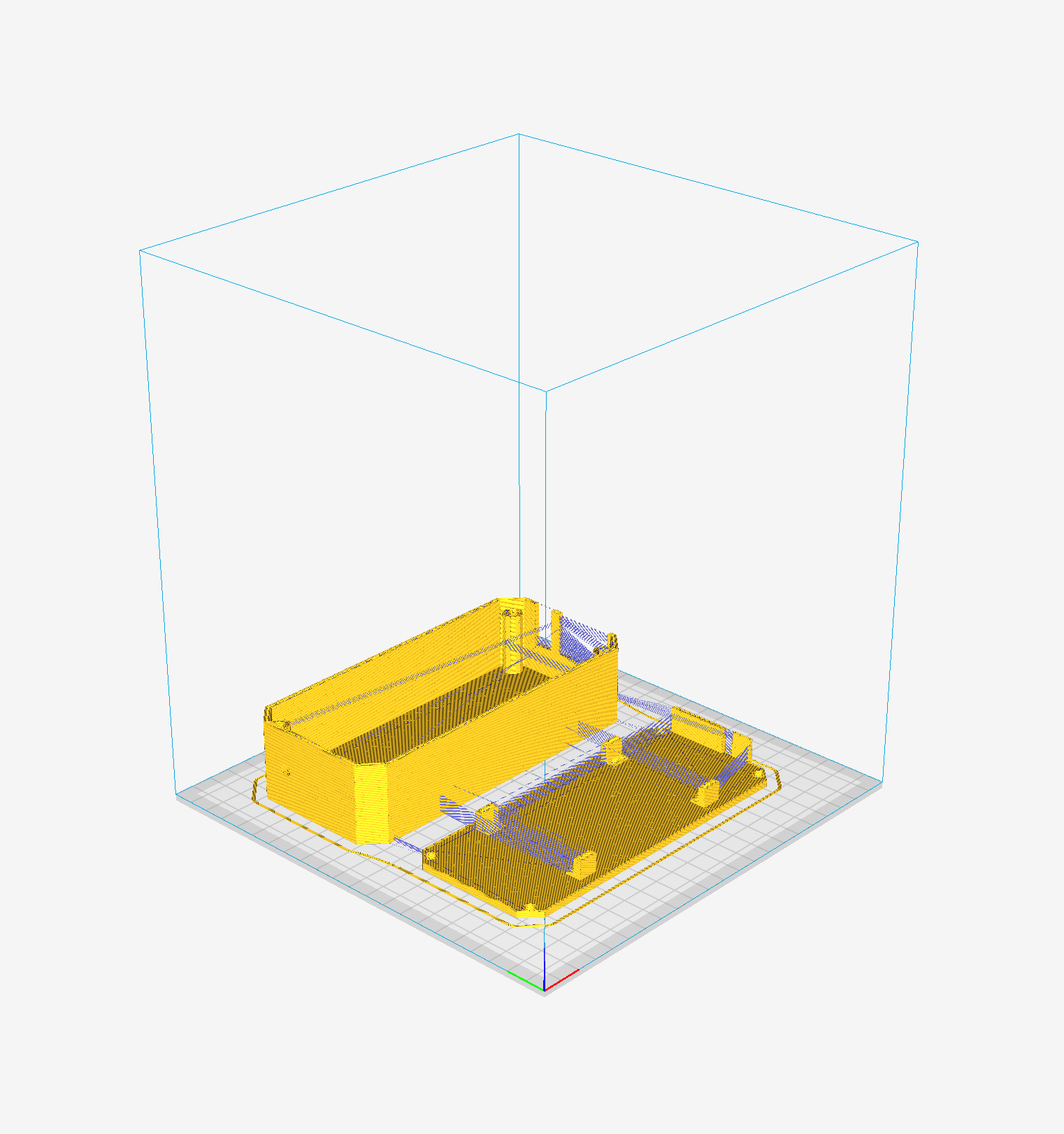
I send the file to my printer and wait for the result.
After 8 hours, this was the result.
Assemble
I have the circuit and enclosure, then I can start to assemble it to the fan. I assemble the three channel switch with a connector to the circuit.
Add the circuit to the base to connect the wires, I needed to cut a little bit the PCB to fit into the base, I did a bad measurement just a few millimeters, I don’t have an excellent tool for measurement.
Connect the fan wires, connect the infrared receiver, and connect two wires to the 9v power supply (In this example a battery).
Then after screw-down, I tried that all it is working correctly.
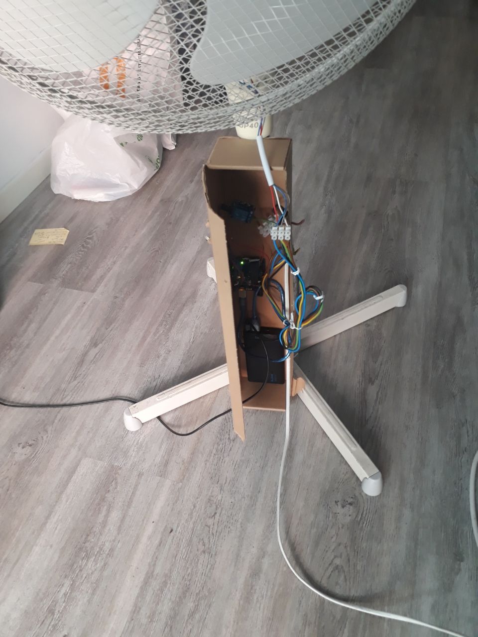
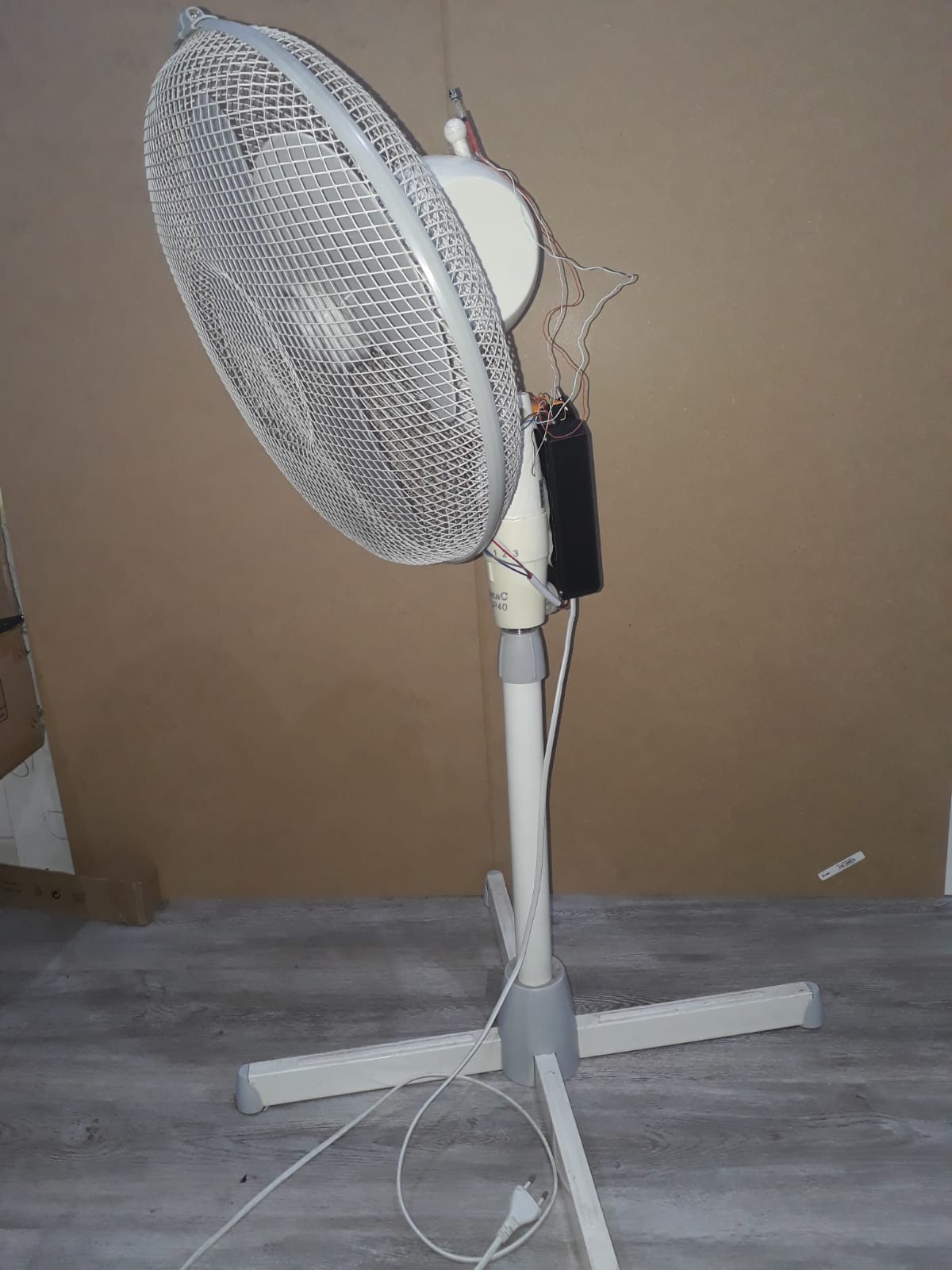
I finished assembling the enclosure and I just need to attach it to my fan.
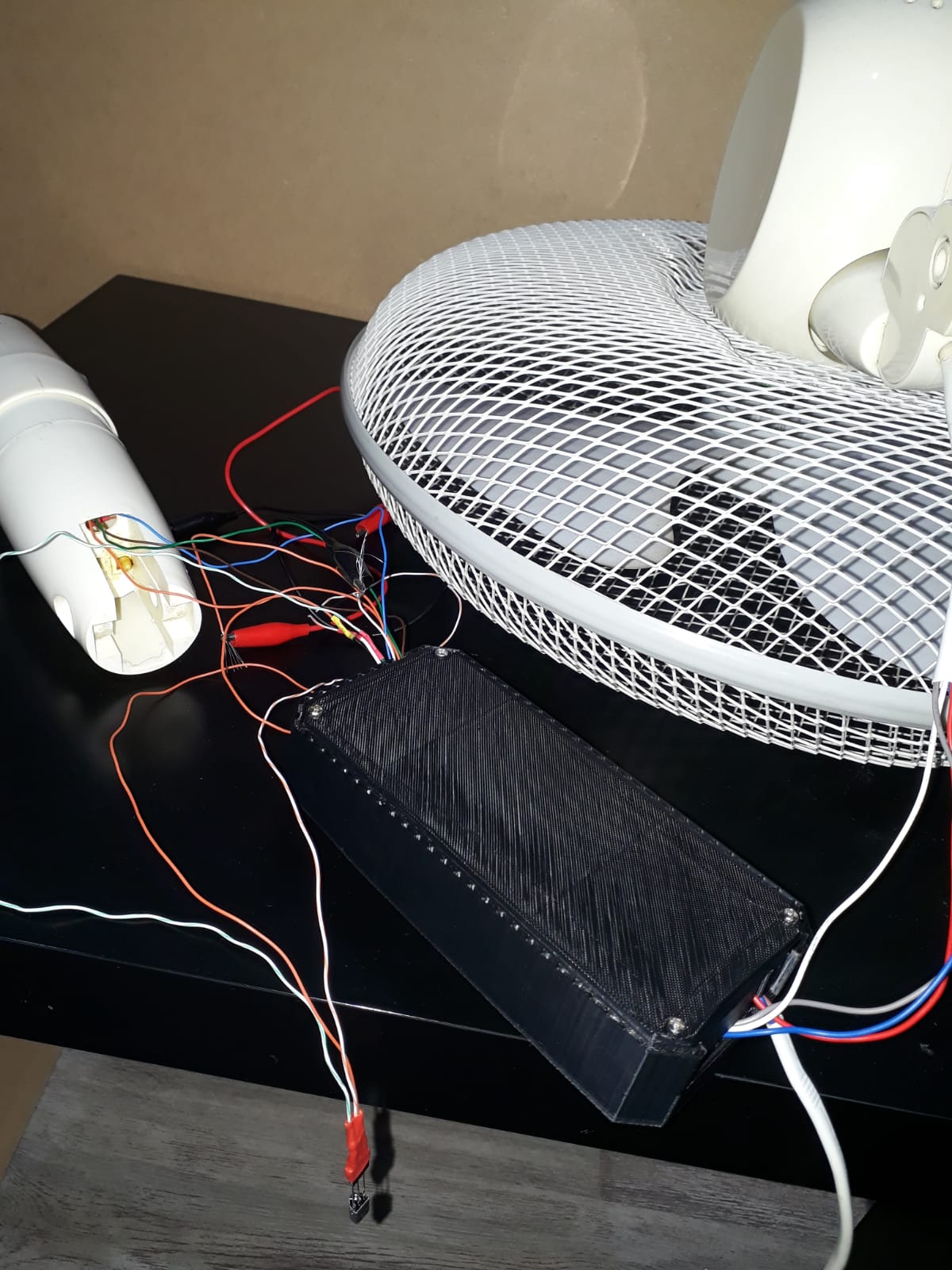
This is the final result, I have put the Infrared receiver behind the fan then when you are looking at the front of it you don’t see the sensor. I have attached the enclosure with adhesive because it is not to be the final enclosure for the next summer then I just add adhesive.
Right now the microcontroller needs a 9v battery to work, I have planned to add an AC-DC converter, I have already one, but I prefer to use in the second version of my fan.
Conclusions
I learned a lot from my first version to the last one. It was an excellent experience from zero knowledge to being able of doing something like this and I will continue working on this kind of projects to more fun.
At the end I did some changes to my circuit, I used different connectors on the cold side like removing the block for the analog input, removing the infrared wires soldered directly to the circuit, I cut one hole to my enclosure for the cold side wires, I use nail polish to improve the isolation in the hot side.
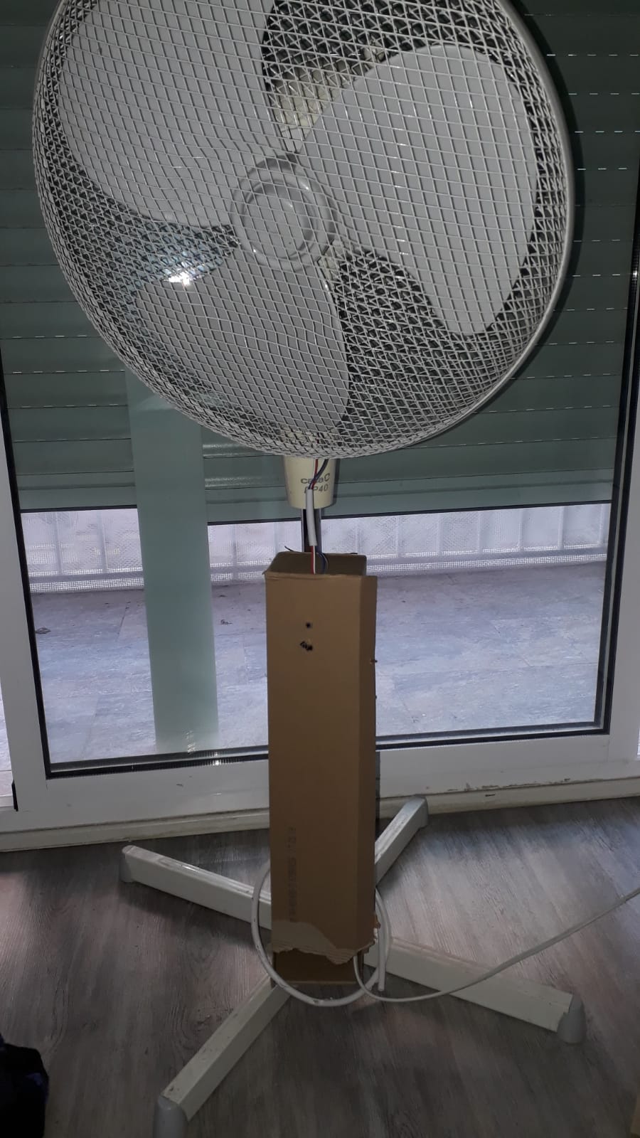 First version
 Second version